English

Need Help Now? Call Us!
+86-0510-83880396
Our team proudly offers an on-time guarantee and a 100% customer satisfaction guarantee.
Contact Online


 Home / News / Industry News / Auxiliary Battery Guide: Types, Charging Systems, Sizing and Replacement
  2026.10.13
 Industry News
A workshop pulls in a four-year-old pickup with start-stop disabled and a dash message reading "battery charging". The main battery passes a conductance test at 720 CCA. The fault sits in a 12 V auxiliary battery under the rear seat, resting at 11.6 V after an overnight soak, fed by a charging circuit that has been delivering only 13.2 V at its terminals for two winters.
Core conclusion: an auxiliary battery is a small, separate reserve, typically 12 V and 7 to 45 Ah, that holds control module memory, supports stop-start restarts and backs up non-critical loads when the main battery or traction pack is offline. It is charged by the same alternator or by a DC-DC converter, and it usually dies from chronic undercharging rather than from age.
Diagnose the charging path before you bill a replacement battery.
The sections below cover what the auxiliary battery actually powers, how it recharges across four common architectures, how to choose a chemistry, and a five-step replacement workflow that removes most repeat visits.
Content
In a dual-battery vehicle the two batteries are not equal partners. The main battery handles cranking and takes the bulk charge. The auxiliary battery covers four jobs:
Capacity is deliberately small. Passenger cars typically use 7 to 20 Ah, trucks and buses 20 to 45 Ah, and rarely more than 60 Ah for deep-cycle auxiliary loads. The auxiliary battery is not expected to crank a cold diesel; it is expected to hold a defined voltage for a defined number of minutes.
Absorbs the short, high-current demands of frequent restarts so the main battery is not cycled dozens of times per day.
Keeps ECU, ADAS and infotainment supply above their reset threshold while the starter draws current from the main battery.
Prevents a flat main battery from taking down safety-relevant and security-relevant circuits that must stay powered.
Four architectures cover almost every vehicle carrying a second battery. The charging source changes; the electrical behaviour does not.
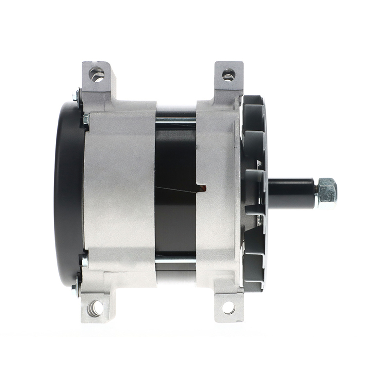
The number that decides auxiliary battery life is the voltage at the battery terminals, not the figure on the alternator label. When an AGM auxiliary battery only ever sees 13.2 V, it stays below roughly 70% state of charge, sulfation begins, and 18-month failures follow. Machines running two banks from one alternator need current headroom to refill the auxiliary bank between work cycles; a 12 V 170 A Delco Remy unit built for Caterpillar equipment exists for exactly that duty.
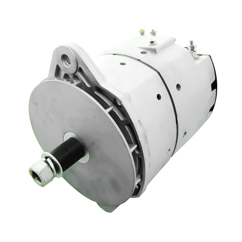 12V 170A Delco Remy Alternator for Heavy TrucksHigh-output 12 V 170 A replacement with OEM cross-reference numbers for Freightliner, International, Kenworth, Peterbilt and Sterling applications; useful when checking charging headroom.View Product →
As a working rule, alternator output should be at least 25% of the combined Ah of both batteries, and the auxiliary feed cable should be sized for the full charge current over its length. Matching a charging source to a battery bank follows the same OE-number logic used elsewhere in the electrical system; published alternator specifications for trucks, agriculture and construction equipment give the voltage, current and pulley data needed to cross-check a bank upgrade before ordering.
Chemistry determines how fast the auxiliary battery accepts charge and how long it survives repeated partial cycling.
Two selection rules prevent most comebacks. First, never downrate chemistry to save cost in a vehicle that charges above 14.4 V, because flooded plates gas and dry out. Second, when replacing an auxiliary battery, match case size, terminal layout, vent path and hold-down, not just Amp-hour rating; a physically correct battery that vents into a sealed cabin is a safety problem, not a bargain.
Datasheets publish Ah and CCA. Three other numbers decide whether a vehicle starts after a two-week park, and they are rarely printed.
The chart shows retained capacity after 14 days at 20 degrees C with a 25 mA parasitic load. The second hidden metric is quiescent drain tolerance: a healthy vehicle should fall below 50 mA within 30 minutes of shutdown, and every 20 mA above that shortens safe parking time proportionally. The third is charge acceptance at 0 degrees C, where AGM recovers roughly 55% of its rated current while flooded recovers about 30%. A winter-short-trip vehicle on flooded chemistry is effectively never fully charged.
Fitting patterns follow vehicle electrification and duty cycle rather than region.
Commercial and off-highway segments matter more than their share suggests, because their auxiliary batteries sit in vibration-heavy, wide-temperature environments and are frequently charged by a single heavy-duty alternator serving two banks. A 24 V 110 A heavy-duty alternator built for trucks, industrial and military vehicles covers that exact combination of dual-bank charging and rough duty.
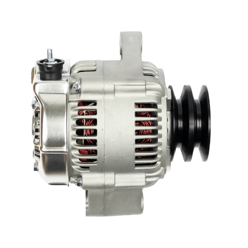
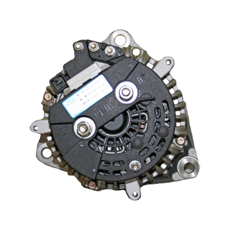 24V 110A Heavy-Duty Alternator for Prestolite TrucksHigh-output 24 V 110 A replacement for Prestolite-equipped trucks, industrial and military vehicles; cross-references AVI144S3001, 860558 and 861318, suited to dual-bank charging.View Product →
Measure resting voltage after an eight-hour soak, then load test at half the rated CCA. Below 12.4 V rested with a normal load result points elsewhere.
Idle and 2000 rpm, loads on. Under 13.5 V on a 12 V system or 27.6 V on a 24 V system means the charging path must be repaired first.
Clamp meter after sleep mode. Above 50 mA warrants a circuit-by-circuit search before any new battery is fitted.
Chemistry, Ah, CCA, terminal layout, case footprint, venting and hold-down. Physical fit is not the same as electrical fit.
Reset the battery management registration, then confirm start-stop resumes and charge voltage settles in range. Skipping registration ages the new battery at roughly double rate.
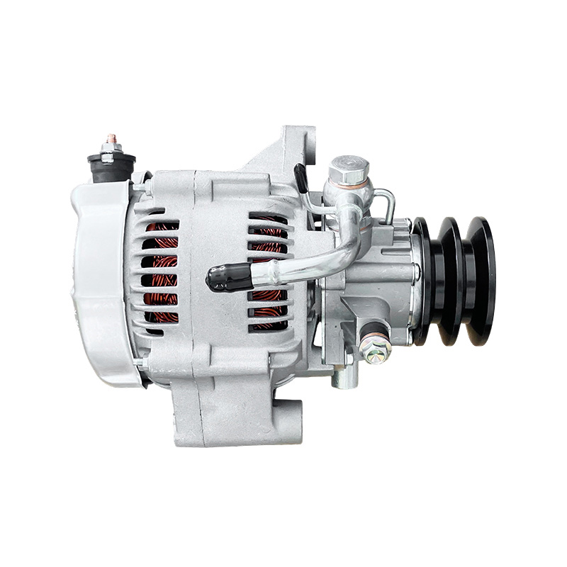
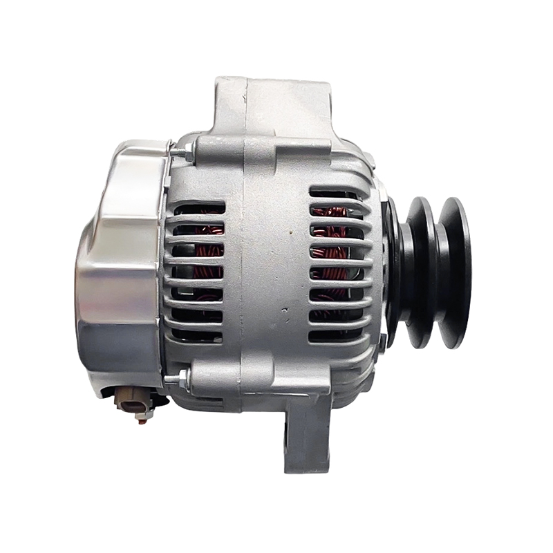
Transport refrigeration and standby systems deserve their own check, since their auxiliary batteries cycle far more often than a car's. A 12 V 105 A alternator for Carrier Transicold Supra units is a typical charging source in that segment, and its output should be verified whenever the auxiliary battery is replaced.
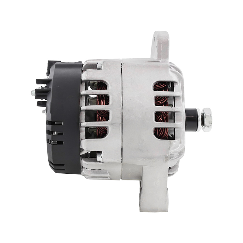 12V 105A Alternator for Carrier Transicold Supra ReefersDrop-in 12 V 105 A replacement for Carrier Transicold Supra reefer units and Kubota V1505/V2203 engines, suited to frequent cycling and auxiliary battery support.View Product →
Auxiliary batteries are simple components in a complicated circuit. The practical takeaways: measure charging voltage at the battery terminals before condemning the battery; expect 0.3 to 0.8 V of loss between alternator and auxiliary feed; match chemistry to the vehicle's charging profile rather than to price; and treat every replacement as a charging-system inspection. Components manufactured to OE cross-reference data, with the voltage, current and pulley specification printed alongside the part number, make that inspection faster than guessing. Done in that order, most auxiliary batteries reach their designed service life instead of returning to the workshop inside two years.
Recommended Products
For Exclusive Offers And The Latest Deals, Feel Free To Contact Us!
We will unswervingly implement the tenet of "quality first, customer first, strict management, and creating a famous brand". Professional OEM/ODM Automotive Alternator Manufacturers and Heavy-Duty Truck Alternators Suppliers in China.
Product
Contact Info.
+86-180 5150 2183
+86-0510-83880396
No. 11 QiBei Road, Yuqi Town, Wuxi City, Jiangsu Province, China
 OEM Alternator Supplier Custom Automotive Alternator Truck Alternators Supplier
 English
 Español
 عربى
عربى