English

Need Help Now? Call Us!
+86-0510-83880396
Our team proudly offers an on-time guarantee and a 100% customer satisfaction guarantee.
Contact Online


 2026.07.21
 Industry News
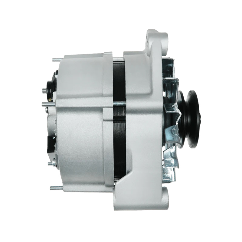
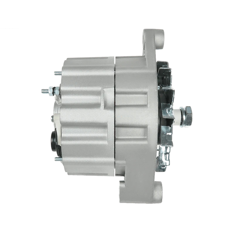
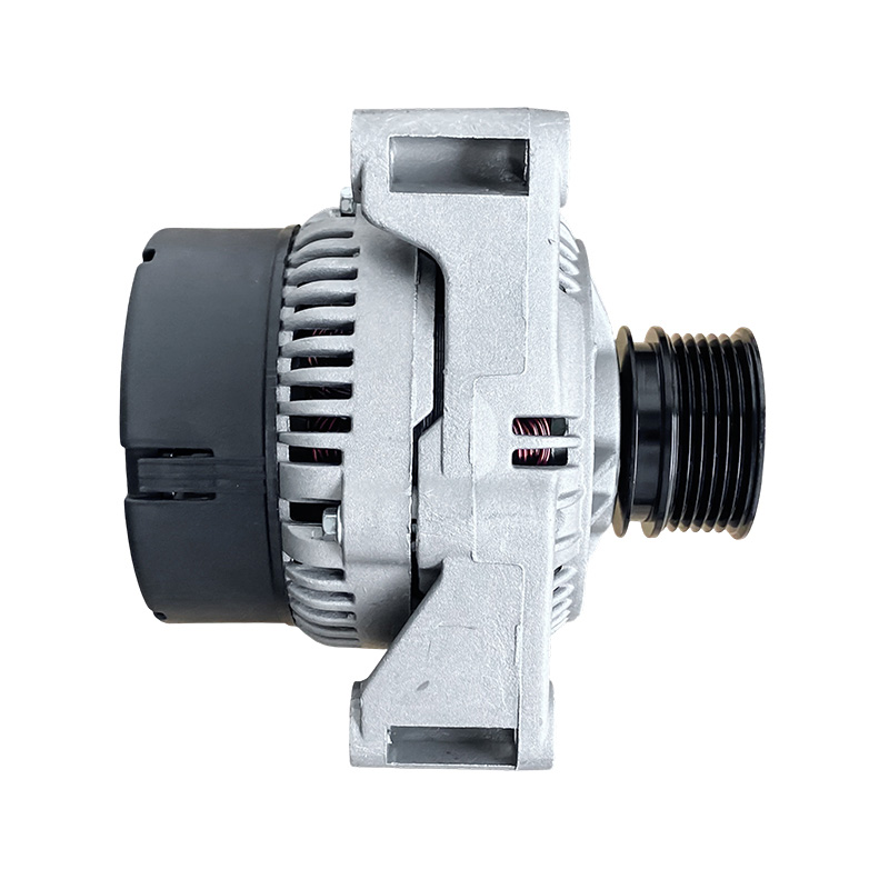
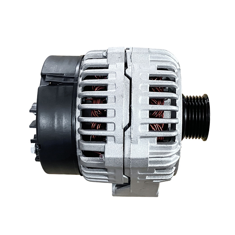
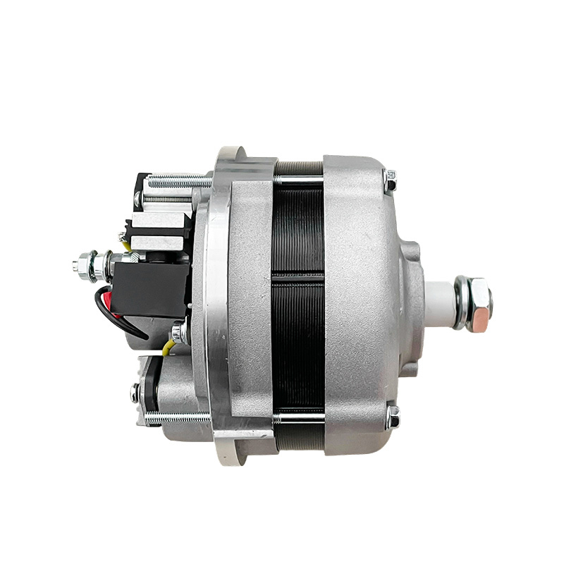
Repairing an Iskra alternator yourself is entirely feasible if you follow a systematic diagnostic and replacement process. The most common failures—worn bearings, a faulty voltage regulator, and scored slip rings—can all be addressed with basic hand tools and a methodical approach. Before ordering parts, confirm the alternator's model number stamped on the housing, typically beginning with AAK, AAN, or IA prefixes. Iskra alternators share a modular construction that allows individual component replacement rather than full unit disposal, keeping repair costs to 30–60% of a new unit's price when the rotor and stator windings remain intact. The following sections walk through diagnosing the fault, disassembling the alternator safely, servicing each wear component, and reassembling with the correct torque values.
Content
A structured diagnosis prevents unnecessary component replacement. Begin with the alternator still mounted on the engine, then proceed to bench testing once removed. Three distinct symptom patterns point to specific failed components.
A warning light that glows dimly at idle but extinguishes above 1,200–1,500 rpm typically signals worn brushes making intermittent contact with the slip rings. A light that stays fully illuminated regardless of engine speed points to a failed voltage regulator or an open diode in the rectifier bridge. No warning light at all, combined with a discharged battery, suggests a broken field circuit or completely worn brushes that have lost all contact. Measure battery voltage at the terminals with the engine running: a healthy Iskra alternator should produce 13.8–14.4 volts at 2,000 rpm. Readings below 13.2 volts under load with lights and heater fan on confirm insufficient charging output.
A grinding or rumbling noise that changes pitch with engine speed almost always indicates a failing bearing. Use a mechanic's stethoscope or a long screwdriver pressed against the alternator housing: a rough, grainy sound at the front bearing (pulley end) is the most common finding, as this bearing absorbs belt tension loads that can exceed 50–70 kg on overtightened drive belts. A high-pitched electrical whine that varies with electrical load rather than rpm suggests a failing diode or regulator oscillating at audible frequency. Remove the drive belt and spin the pulley by hand: any roughness, catching, or axial play exceeding 0.5 mm confirms bearing replacement is needed.
Disconnect the battery negative terminal before touching any alternator wiring—the main B+ terminal carries unfused battery voltage directly, and accidental grounding against the engine block can cause a short circuit with enough current to weld a spanner. On Iskra units fitted to agricultural machinery, the mounting bolts may be metric sizes: M8 or M10 bolts with 13 mm or 17 mm heads are standard. Penetrating oil applied 15–30 minutes before loosening reduces the risk of snapping a bolt in the cast aluminum bracket. Photograph the wiring connections before removal; Iskra alternators may use a three-pin plug for the regulator sense, warning light, and ignition feed, plus a separate ring terminal for the main output. Label each wire if the connector housing is degraded.
Iskra alternators follow a standard construction that separates into front and rear housings once the four through-bolts are removed. The sequence is consistent across AAK and IA series models.
With the alternator disassembled, inspect each component methodically. Replace any part that falls outside the acceptable ranges below rather than attempting to extend its service life; a single weak component will cause the rebuilt alternator to fail prematurely.
The two copper slip rings on the rotor shaft transfer field current to the rotating field coil. Over time, brush friction wears grooves into the ring surface. Measure the ring diameter with calipers: most Iskra rotors have a new slip ring diameter of 28–32 mm, and the minimum acceptable diameter is typically 2 mm below the original specification. If grooves deeper than 0.3 mm are present but the diameter remains within limits, the rings can be refinished on a lathe with fine emery cloth. If the diameter is below minimum or the rings are deeply scored, replace the rotor assembly or have new rings installed by an auto-electric specialist. Measure resistance between the two slip rings: expect 2.5–4.0 ohms on most 12V Iskra models. An open circuit indicates a broken field coil wire; zero ohms indicates a shorted coil.
The regulator and brush holder are typically a single integrated unit on Iskra alternators, mounted to the rear housing with two small screws. Remove it and measure the brush length protruding from the holder: new brushes are 12–15 mm long, and the wear limit is 5 mm. Brushes shorter than 5 mm cannot maintain reliable spring pressure against the slip rings, producing intermittent charging. Check that the spring-loaded brushes move freely in their guides; sticking brushes are a common cause of flickering charge warning lights. The regulator itself can be bench-tested by connecting a variable DC power supply across the field terminals and verifying that it switches at 14.2–14.5 volts. A regulator that remains open-circuit above this voltage or fails to switch at all must be replaced as a complete unit.
Iskra alternators use standard metric bearings. The front bearing is typically a 6203-2RS (40 mm OD, 17 mm bore, 12 mm width) sealed ball bearing, while the rear bearing is often a 6201-2RS (32 mm OD, 12 mm bore, 10 mm width) or a needle roller bearing depending on model. The bearing reference number is etched into the metal shield of the old bearing. Use only 2RS (double rubber sealed) or 2Z (double metal shielded) bearings rated for at least 12,000 rpm. Agricultural and industrial Iskra applications subject the front bearing to dust and moisture; a sealed bearing with a high-temperature lithium grease fill resists contamination better than an open bearing. Press the old bearing off and the new bearing on using a socket that contacts only the inner race—pressing on the outer race transmits force through the balls and damages the new bearing instantly.
The rectifier bridge converts the stator's AC output to DC. It contains six or eight diodes pressed into aluminum heat sinks. Test each diode individually with a multimeter set to diode mode. With the alternator fully disconnected from the stator, place the positive probe on the diode anode and the negative probe on the cathode: a healthy diode shows 0.4–0.7 volts forward bias and open circuit in reverse. A shorted diode reads near zero in both directions; an open diode shows no reading in either direction. A single failed diode reduces alternator output by roughly 30% and introduces AC ripple that confuses engine ECUs and damages batteries. If one diode has failed, replace the entire rectifier assembly rather than attempting individual diode replacement—the labor of pressing out and soldering individual diodes rarely justifies the marginal cost savings over a new rectifier unit.
| Component | Typical Specification | Failure Threshold | Replace or Repair |
|---|---|---|---|
| Brushes | 12–15 mm length | Below 5 mm | Replace regulator assembly |
| Slip Rings | 28–32 mm diameter | 2 mm below original OD | Refinish or replace rotor |
| Rotor Field Coil | 2.5–4.0 ohms | Open or short circuit | Replace rotor |
| Front Bearing | 6203-2RS | Noise, play >0.5 mm | Replace bearing |
| Voltage Regulator | Switches at 14.2–14.5V | No switching or wrong voltage | Replace regulator |
Clean all housing mating surfaces before reassembly; corrosion between the housings can prevent proper grounding of the rear housing to the engine. Solder the stator leads to the rectifier using rosin-core electrical solder—never acid-core plumbing solder, which corrodes copper connections. Position the regulator with its brushes retracted or held back with a retaining pin if the design includes one. Align the front and rear housings according to the marks made during disassembly and insert the four through-bolts, tightening them gradually in a cross pattern to 5–8 Nm. Over-tightening strips the aluminum housing threads. Install the pulley and tighten the nut to 65–80 Nm while holding the rotor shaft. Spin the pulley by hand after reassembly: the rotor should turn smoothly with a slight resistance from the brushes contacting the slip rings, with no scraping or tight spots.
Before reinstalling, connect the alternator to a battery and spin it with a drill to verify output. Connect the B+ terminal to battery positive through a 10-amp fused lead, connect the housing to battery negative, and supply 12 volts to the ignition or sense terminal (usually marked D+ or S). Spin the alternator at approximately 2,500–3,000 rpm with a drill and socket on the pulley nut. The output voltage should rise to 13.8–14.4 volts within seconds. If the voltage does not rise, recheck the regulator connections and brush contact. Install the repaired alternator, reconnect the wiring exactly as photographed, tighten the mounting bolts to the manufacturer's specification (typically 25–35 Nm for M8 and 45–55 Nm for M10), and adjust the drive belt to allow 10–15 mm deflection under firm thumb pressure at the midpoint between pulleys. A belt tensioned too tightly will destroy the new front bearing within months, repeating the original failure.
Recommended Products
For Exclusive Offers And The Latest Deals, Feel Free To Contact Us!
We will unswervingly implement the tenet of "quality first, customer first, strict management, and creating a famous brand". Professional OEM/ODM Automotive Alternator Manufacturers and Heavy-Duty Truck Alternators Suppliers in China.
Product
Contact Info.
+86-180 5150 2183
+86-0510-83880396
No. 11 QiBei Road, Yuqi Town, Wuxi City, Jiangsu Province, China
 OEM Alternator Supplier Custom Automotive Alternator Truck Alternators Supplier
 English
 Español
 عربى
عربى